What is Tg in PCB Materials?
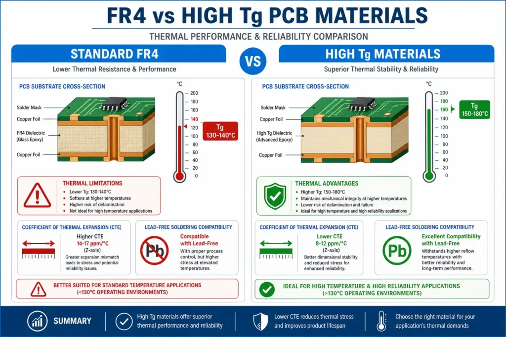
Tg (Glass Transition Temperature) is the critical temperature at which a polymer-based PCB substrate transitions from a rigid, glassy state to a softer, rubbery state. Below Tg, the material maintains its dimensional stability and mechanical strength. Above Tg, the material’s stiffness decreases significantly, and coefficients of thermal expansion (CTE) increase substantially.
Understanding Tg is essential because the PCB operates in thermal environments throughout its lifecycle:
- Assembly — Reflow soldering exposes boards to peak temperatures
- Operation — Environmental and component-generated heat
- Field Conditions — Temperature fluctuations during use
Per IPC-4101, the base material specification standard, FR4 materials are classified by their Tg ratings. Standard FR4 falls into categories with Tg values of approximately 130°C, while high Tg materials are designated at 150°C, 170°C, or higher.
Critical design rule: Operating temperature should typically remain 20-30°C below the material’s Tg to maintain mechanical integrity.
Standard FR4 PCB Material
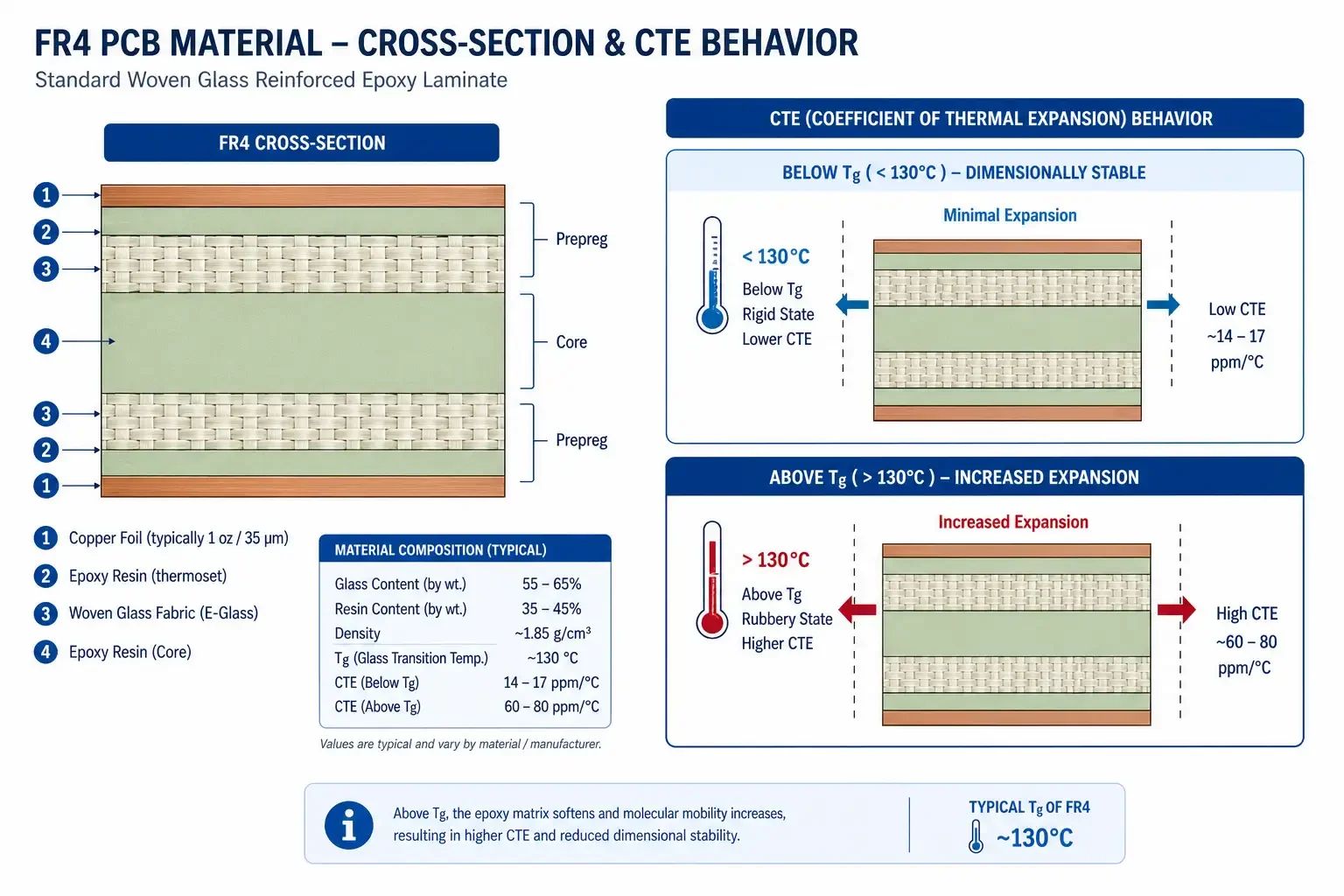
Standard FR4 (Flame Retardant 4) is the most widely used PCB substrate material in the electronics industry, accounting for over 90% of all PCB production volume. It consists of woven fiberglass fabric impregnated with epoxy resin.
Properties of Standard FR4
| Property | Value |
|---|---|
| Glass Transition (Tg) | 130-140°C |
| Decomposition Temp (Td) | 260-280°C |
| CTE Z-axis (below Tg) | 50-60 ppm/°C |
| CTE Z-axis (above Tg) | 150-250 ppm/°C |
| Typical Thickness Range | 0.2mm – 3.2mm |
| Cost Index | 1.0x (baseline) |
| Shelf Life | 12 months |
Typical Applications
Standard FR4 is used extensively in consumer electronics, computer peripherals, industrial control boards with standard thermal requirements, prototypes and low-to-medium volume production, single and double-sided boards, and standard multilayer boards (4-12 layers) with mild thermal demands.
Limitations
Standard FR4 faces challenges in high-temperature applications because its Tg of 130-140°C provides limited margin when lead-free reflow profiles reach 245-260°C peak temperatures. During thermal cycling, the large CTE mismatch between copper (17 ppm/°C) and FR4 substrate creates mechanical stress at plated through-holes and pad interfaces.
High Tg PCB Material
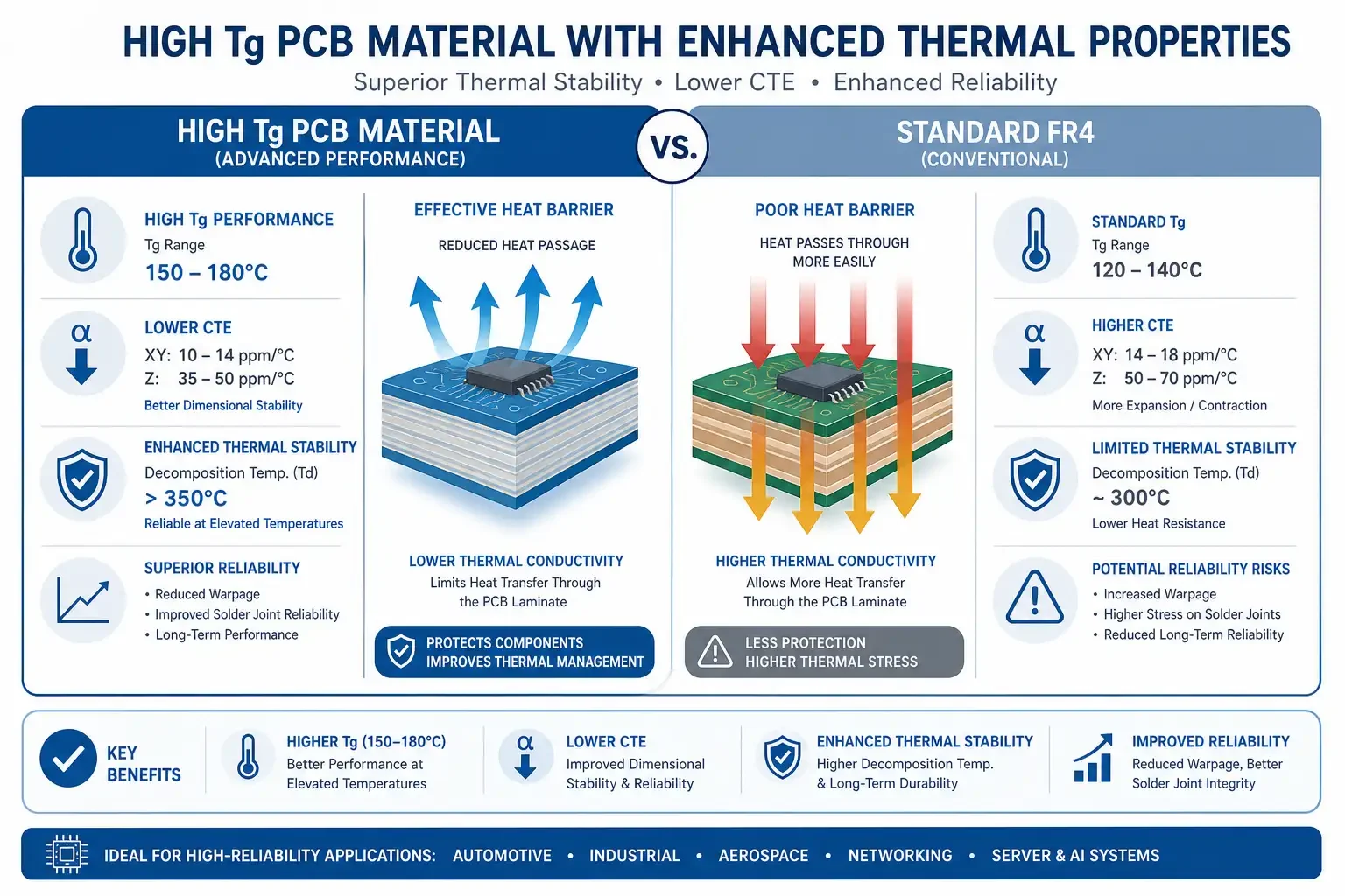
High Tg PCB materials are engineered substrates with enhanced thermal resistance, designed for applications requiring superior thermal performance. These materials maintain their mechanical properties at temperatures significantly higher than standard FR4.
Properties of High Tg Materials
| Property | Value (High Tg) |
|---|---|
| Glass Transition (Tg) | 150-180°C |
| Decomposition Temp (Td) | 280-340°C |
| CTE Z-axis (below Tg) | 40-50 ppm/°C |
| CTE Z-axis (above Tg) | 100-150 ppm/°C |
| Typical Tg Grades | 150°C, 170°C, 180°C |
| Cost Index | 1.3-1.8x vs FR4 |
| Shelf Life | 12 months |
Common High Tg Material Brands
- Isola: I-Speed, I-Tera (mid-Tg and high-Tg products)
- Nelco: N4000-13, N4800-20
- Rogers: RO4000 series (high-frequency, some high-Tg options)
- Shengyi: S1000-2, S703G
Advantages
- Lead-free soldering compatibility — Higher Tg provides thermal margin for SnAgCu (SAC) alloys
- Reduced warpage — Better dimensional stability during assembly
- Improved thermal cycling — Lower CTE reduces stress on vias and pads
- Enhanced reliability — Better performance in thermally demanding environments
- Broader processing window — More tolerant of temperature variations
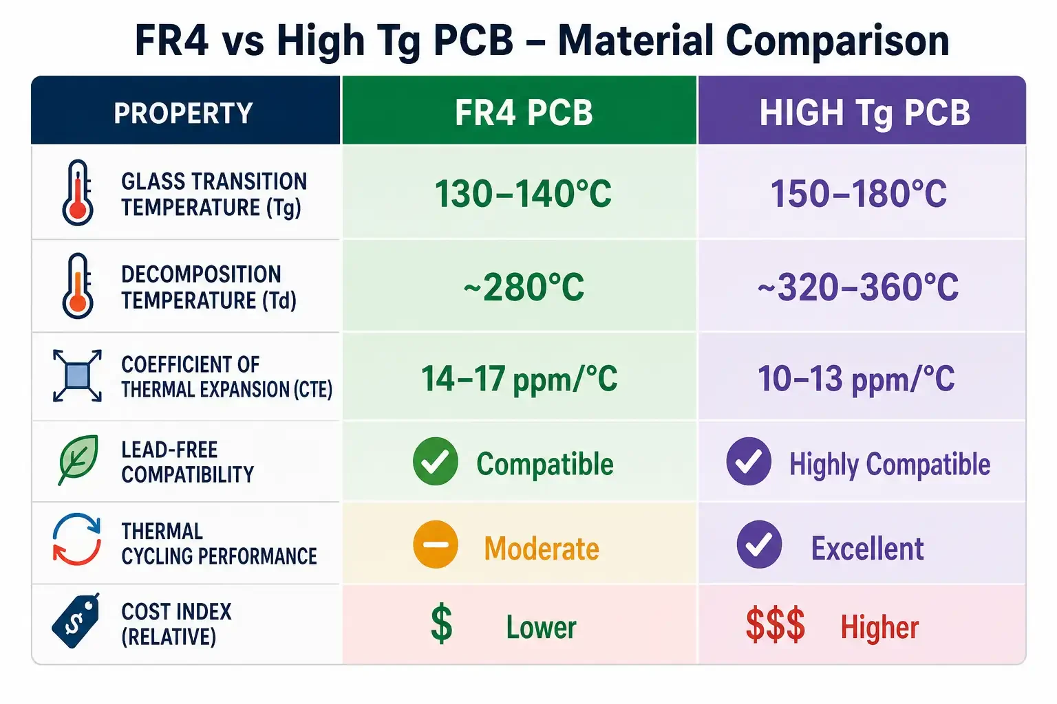
FR4 vs High Tg: Key Differences Comparison
| Parameter | Standard FR4 | High Tg FR4 |
|---|---|---|
| Glass Transition (Tg) | 130-140°C | 150-180°C |
| Decomposition Temp (Td) | 260-280°C | 280-340°C |
| Z-axis CTE | 50-60 ppm/°C | 40-50 ppm/°C |
| Lead-free Soldering | Marginal | Excellent |
| Thermal Cycling | Moderate | Excellent |
| Typical Layers | 1-12 | 4-20+ |
| Board Thickness | Up to 3.2mm | No practical limit |
| Cost | Baseline (1.0x) | 1.3-1.8x |
| Lead Time | Standard | Standard to +1-2 days |
| Applications | Consumer, standard | Automotive, aerospace, industrial |
Key Differentiators
Thermal Performance: High Tg materials demonstrate 30-50% lower Z-axis CTE expansion, significantly reducing stress on plated through-holes (PTH) during thermal cycling. This translates to fewer field failures in demanding applications.
Lead-free Compatibility: The European Union RoHS directive mandates lead-free soldering in most electronics. Standard FR4 can handle lead-free processes but with reduced manufacturing yields. High Tg materials provide the thermal headroom needed for reliable lead-free assembly.
Cost Trade-off: While high Tg costs 30-80% more, the premium is justified when assembly yield improvements offset material cost, field failure costs are unacceptable, or customer specifications require specific Tg ratings.
When to Choose Standard FR4
Choose standard FR4 when budget constraints dominate, thermal requirements are modest, conventional lead-based soldering is used, standard qualification requirements apply (IPC-6012 Class 2 or lower), prototype or short-run production is needed, or board construction is simple with low layer count and standard features.
Typical FR4 Applications
- Consumer electronics chargers and adapters
- LED lighting control boards
- Audio equipment and speakers
- Computer accessories and peripherals
- Basic IoT devices
When to Choose High Tg PCB Material
Choose high Tg materials when lead-free soldering is required (RoHS compliance), elevated operating temperatures exceed 100°C, board thickness exceeds 2.5mm, layer count is 16 or higher, automotive applications require AEC-Q200 and IPC-6012 Class 3, thermally demanding environments (industrial, outdoor, aerospace), multiple reflow cycles are expected (3+ passes), or long product lifecycle with 5-10+ year reliability requirements.
Typical High Tg Applications
- Automotive ECUs — Engine control units with high under-hood temperatures
- Electric vehicle charging — On-board chargers and DC-DC converters
- Industrial motor drives — Variable frequency drives with thermal cycling
- Power supplies — Server power, UPS systems with high thermal loads
- Aerospace systems — Avionics with strict thermal and reliability requirements
- LED lighting (high power) — Street lighting, automotive headlights
- Telecom infrastructure — Base station equipment with outdoor thermal exposure
Thermal Performance Considerations
Beyond Tg, several thermal parameters affect PCB material selection:
Decomosition Temperature (Td)
Td is the temperature at which the material loses 5% of its weight. High Td materials provide additional safety margin during assembly:
| Material | Typical Td |
|---|---|
| Standard FR4 | 260-280°C |
| Mid-Tg (150°C) | 300-320°C |
| High-Tg (170°C+) | 320-340°C |
Coefficient of Thermal Expansion (CTE)
CTE mismatch between copper and substrate causes mechanical stress. Lower CTE materials reduce via barrel cracking, pad lift-off, delamination, and interfacial failures.
Thermal Cycling Performance
High Tg materials typically survive 2-3x more thermal cycles than standard FR4 before failure, making them essential for applications with frequent temperature fluctuations.
Cost Implications
Material selection involves balancing performance requirements against cost constraints:
Direct Material Cost
| Material | Relative Cost |
|---|---|
| Standard FR4 | 1.0x |
| Mid-Tg (150°C) | 1.3-1.4x |
| High-Tg (170°C) | 1.5-1.6x |
| Ultra High-Tg (180°C) | 1.7-1.8x |
Total Cost Considerations
Beyond raw material cost, consider assembly yield improvements with high Tg (typically 2-5% improvement for lead-free), field failure costs and warranty implications, qualification requirements for specific industries, and supply chain availability and lead time.
For high-volume consumer products, standard FR4 with careful process control often suffices. For automotive and industrial applications, high Tg’s premium is typically justified by reliability requirements.
Frequently Asked Questions
What does Tg mean in PCB materials?
Tg (Glass Transition Temperature) is the temperature at which a polymer changes from a rigid, glassy state to a softer, rubbery state. For PCB applications, operating temperatures should remain 20-30°C below Tg to ensure dimensional stability and mechanical integrity. Standard FR4 has Tg around 130-140°C, while high Tg materials range from 150-180°C.
When should I use high Tg PCB material instead of standard FR4?
Use high Tg when lead-free soldering is required (reflow temperatures up to 260°C), operating environment exceeds 100°C, board thickness exceeds 2.5mm, layer count is 16 or higher, or your industry specification mandates it (automotive AEC-Q200, aerospace). High Tg provides thermal margin that prevents warpage, delamination, and via failures.
What is the cost difference between FR4 and high Tg?
High Tg materials typically cost 30-80% more than standard FR4, depending on the specific Tg rating. Mid-Tg (150°C) materials are approximately 30-40% higher, while high-Tg (170-180°C) materials range from 50-80% premium. This cost is often justified by improved assembly yields and field reliability in thermally demanding applications.
Can standard FR4 handle lead-free soldering?
Standard FR4 (Tg 130°C) can handle lead-free soldering but with limitations. The peak reflow temperature for SAC (SnAgCu) alloys is 245-260°C, which provides minimal margin above standard FR4’s Tg. For reliable lead-free assembly with acceptable yields, high Tg materials (Tg ≥150°C) are recommended.
What Tg rating do automotive PCBs require?
Automotive applications typically require Tg ≥150°C per IPC-6012 Class 3 qualification requirements. Under-hood applications may require Tg of 170°C or higher due to sustained high temperatures. AEC-Q200 defines component stress test qualifications, while IPC-6012 governs PCB qualification including material requirements.
References
- IPC-4101, “Specification for Base Materials for Rigid and Multilayer Printed Boards,” IPC, 2024.
https://www.ipc.org/ - IPC-6012, “Qualification and Performance Specification for Rigid Printed Boards,” IPC, 2024.
https://www.ipc.org/ - Isola Group, “High Tg Materials for Lead-Free Assembly,” Product Technical Data Sheets, 2025.
- K. G. C. Wyborn, “Thermal Management in High-Density Multilayer PCBs,” Circuit World, Vol. 47, No. 3, 2021.
Further Reading
- Custom PCB Manufacturer — Find a manufacturer for your FR4 or high Tg PCB requirements
- PCB Stackup Design — Learn how material selection affects board stackup
- PCB Quote Requirements — Specify material requirements in your RFQ
CtrlCPCB | Shanghai Huangte Technology Co., Ltd. | Last updated: 2026-07-23
This article is for informational purposes. Consult with your PCB manufacturer to determine the optimal material for your specific application requirements, thermal profile, and reliability targets.