
Why Documentation Matters for Assembly
When you submit files for prototype PCB assembly, the documentation you provide determines how quickly and accurately the assembly provider can quote and produce your boards. Incomplete files cause quote delays ranging from hours to days, while incorrect files lead to assembly errors that require costly rework.
The assembly process begins with file review. Your assembly provider examines Gerber files to understand board dimensions and layer count, verifies component availability against your BOM, and uses the centroid file to program pick-and-place equipment. Each file serves a specific purpose in this workflow. Missing or incorrect files disrupt the entire process.
Beyond quote accuracy, proper documentation ensures the assembly house sources correct components. A BOM with only “10K resistor” tells the provider nothing actionable—they need manufacturer part numbers like “RC0402FR-0710KL” to verify availability and pricing. Similarly, centroid files must match your BOM exactly; mismatched reference designators cause placement errors that damage boards and components.
For engineers new to contract manufacturing, understanding documentation requirements prevents common mistakes that delay projects. Turnkey PCB assembly services often include file verification, but providing accurate files from the start saves time regardless of your service model.
Essential Files for PCB Assembly
Every prototype PCB assembly submission requires four essential file types. These files contain all information needed for the assembly house to fabricate your PCBs, source components, and assemble your boards.
Gerber Files: These are the manufacturing files that define your PCB. They contain copper traces, solder mask openings, silkscreen markings, and board outline. Gerber format (specifically RS-274X extended Gerber) is the industry standard accepted by virtually all manufacturers.
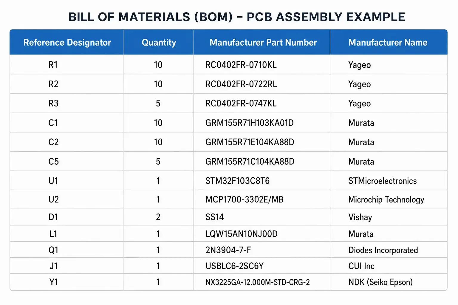
Bill of Materials (BOM): Your BOM lists every component on the board with sufficient detail for procurement. This includes reference designators, quantities, manufacturer part numbers, and manufacturer names. The BOM drives component sourcing—without accurate part numbers, providers cannot verify availability or generate accurate quotes.
Centroid File (XY Data): This file tells the pick-and-place machine where to place each surface mount component. It contains X/Y coordinates, rotation angles, and package information for every SMT part. Without a centroid file, automated assembly is impossible.
NC Drill File: Drill files (in Excellon format) define hole locations and sizes for through-hole components and vias. This file tells the manufacturing equipment where to drill or route holes in the board.
Beyond these essentials, additional files improve accuracy: assembly drawings show component orientation and special placement requirements, test specifications define functional testing requirements, and alternative part suggestions help when primary components are unavailable.
Gerber Files: The Manufacturing Blueprint
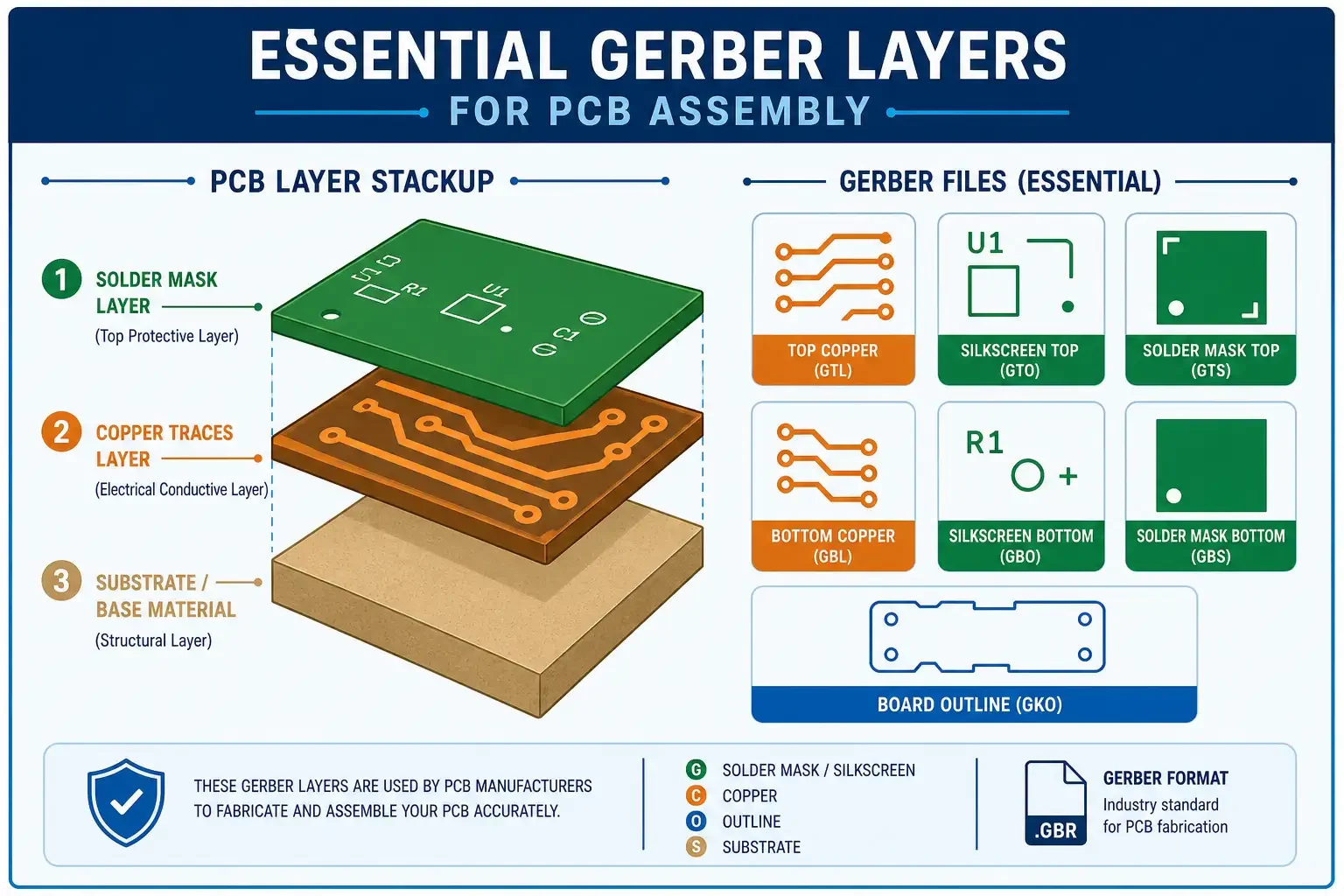
Gerber files are the universal language of PCB manufacturing. These files describe every layer of your board in a format that manufacturing equipment can interpret. Understanding what constitutes a complete Gerber package prevents manufacturing errors and quote delays.
The essential Gerber layers include:
Copper Layers: These define conductive traces on each layer. For single-sided boards, you need only a top copper layer. Double-sided boards require top and bottom copper layers. Multilayer boards add inner layer copper files.
Solder Mask Layers: Solder mask protects copper traces from oxidation and prevents solder bridges. You need top and bottom solder mask files, typically in the same format as copper layers but representing openings rather than metal.
Silkscreen Layers: Silkscreen adds component designators, logos, and other markings to the board. Top and bottom silkscreen files include component outlines, reference designators like R1 or U1, and any special markings.
Board Outline: The board outline layer defines the physical shape of your PCB. This file is critical for routing the board from panelized manufacturing sheets.
Paste Stencil Layers (Optional but Recommended): For surface mount boards, paste layers define where solder paste should be applied. These files generate the stencil used in SMT assembly.
Gerber format RS-274X (extended Gerber) is the current standard. This format embeds aperture definitions within the file, eliminating compatibility issues that plagued older RS-274D format. When exporting from your CAD tool, select RS-274X output.
Common Gerber issues include missing layers (especially paste or board outline), incorrect file format (using old RS-274D), and zero-size apertures. Most modern PCB design software exports RS-274X correctly, but always verify your output before submission.
Bill of Materials (BOM) Requirements
Your Bill of Materials is the most critical file in your assembly package. It drives component procurement—errors here cascade through the entire project. A complete BOM with manufacturer part numbers ensures accurate quotes and correct assembly.
Minimum Required BOM Fields
| Field | Example | Notes |
|---|---|---|
| Reference Designator | R1, C5, U1 | Must match design files exactly |
| Quantity | 10, 100 | Number of each part per board |
| Manufacturer Part Number | RC0402FR-0710KL | Full MPN, not generic value |
| Manufacturer Name | Yageo, Samsung | Company producing the part |
Beyond these minimum fields, recommended additions improve accuracy:
Description: Brief component description like “10K Ohm Resistor 1% 0402” helps verification but should not replace the MPN.
Package/Footprint: Indicates component size—0805, QFN-32, SOIC-8—helping the provider verify correct parts.
Alternate Part Numbers: Lists acceptable substitutes. If your preferred part is unavailable, alternates enable sourcing without delays.
Unit Cost (Optional): Including unit cost helps the provider verify pricing reasonableness.
BOM Format: Export your BOM in CSV or Excel format (.csv or .xlsx). These formats are easily imported into procurement systems. PDF BOMs are difficult to process and often cause errors.
The most common BOM error is using generic descriptions instead of manufacturer part numbers. “10K resistor” is useless for procurement—the provider cannot know which 10K resistor you mean. “Yageo RC0402FR-0710KL” tells the provider exactly what to order. Another frequent error is reference designator mismatches between BOM and Gerber files—always verify consistency before submission.
Centroid File: SMT Placement Data
The centroid file—also called XY data, pick-and-place file, or placement file—contains the information needed to program SMT pick-and-place machines. Without accurate centroid data, components are placed incorrectly, causing assembly failures.
A centroid file specifies for each component: X and Y coordinates defining placement position on the board, rotation angle in degrees (0-360), and package type or height for clearance verification. The IPC-356 standard defines the industry format for centroid data exchange.
IPC-356 Centroid Format
| Field | Example | Description |
|---|---|---|
| RefDes | U1 | Component reference designator |
| X | 25.4000 | X coordinate in mm |
| Y | 50.8000 | Y coordinate in mm |
| Rotation | 180 | Rotation in degrees |
| Package | QFN-32 | Component package type |
| Height | 1.20 | Package height in mm (optional) |
Centroid files must exactly match your BOM. If your BOM lists “U1” as an op-amp, the centroid file must also list “U1” with the correct coordinates. Reference designator mismatches cause assembly errors—components placed on wrong pads or wrong components placed on correct pads.
Common centroid errors include incorrect rotation angles (components oriented 90 degrees off), flipped packages (mirror image placement), and missing components (SMT parts not included in centroid file). Always verify centroid rotation for polar components like diodes, electrolytic capacitors, and ICs with pin 1 indicators.
Most PCB design software exports centroid data automatically. From Altium Designer, Eagle, KiCad, or other popular tools, look for “Export” or “Outputs” menus offering “Centroid” or “Pick and Place” file generation. Verify the output format matches IPC-356 or check with your assembly provider for their preferred format.
Drill Files and Additional Files
Beyond Gerber, BOM, and centroid files, several additional files improve assembly accuracy and enable special requirements.
NC Drill File (Excellon Format): The Numerical Control (NC) drill file defines hole locations, sizes, and plating requirements. Excellon format is the universal standard for drill files. This file tells manufacturing equipment where to drill holes for through-hole components, vias, and mounting holes. Missing drill files mean no holes—components cannot be inserted and vias remain incomplete.
NC Drill files specify:
- Hole locations (X/Y coordinates)
- Hole sizes (diameter)
- Plated or non-plated indication
- Drill hit count for tooling
Assembly Drawings: These documents show component placement, orientation, and any special assembly instructions not evident from the design files. Assembly drawings are especially valuable for boards with polarized components (diodes, ICs with pin 1 markings), mechanical fits requiring precise positioning, and hand-assembly operations or cable routing.
Test Specifications: For functional testing requirements, provide test procedures, acceptance criteria, and any test fixture specifications. Without test specs, the assembly provider performs standard continuity and hipot testing only.
Configuration Files: Some providers request pick-and-place machine configuration files or stencil opening definitions. Ask your assembly provider for their specific requirements.
Format Considerations: Store all files in commonly accepted formats—Gerber (RS-274X), CSV, Excel, PDF, and Excellon are universally accepted. Proprietary CAD formats (like native Altium or Eagle files) are generally not useful for manufacturing.
File Format Best Practices
Following consistent file preparation practices prevents errors and speeds up the quote process. These best practices apply across all file types.
Naming Conventions: Use clear, descriptive filenames that include: project or product name, file type (GERBER, BOM, CENTROID, DRILL), and revision designation (RevA, RevB, or date). Example: “ProductX_Gerber_RevA.zip” or “ProjectY_BOM_2026-08-08.xlsx.” Consistent naming helps both you and the assembly provider track revisions.
Revision Control: Always submit current revision files. Using outdated Gerber files while submitting a current BOM guarantees mismatch errors. Include revision numbers in filenames and on title blocks within drawings. When updating files, notify your assembly provider of the revision change.
Archive Previous Revisions: Keep a record of previous file revisions. When problems arise, comparing current and previous files identifies what changed. Cloud storage or version control systems make revision management straightforward.
File Compression: Compress multiple files into a single archive (.zip or .rar) for upload. This prevents file separation during transfer and simplifies the submission process. Organize the archive logically—Gerber files in one folder, documentation in another.
Verify Before Submission: Before sending files to an assembly house, perform your own verification: open Gerber files in a free viewer like Gerbv to check layer integrity, verify BOM reference designators match design files, and confirm centroid file includes all components.
Common Documentation Mistakes to Avoid
Documentation errors delay quotes, increase costs, and cause assembly defects. Avoiding these common mistakes speeds your path to finished boards.
Mistake 1: Missing or Wrong Manufacturer Part Numbers
Using generic descriptions like “100uF capacitor” instead of “Panasonic EEE-1CA101P” prevents accurate quoting and sourcing. Always include full manufacturer part numbers.
Mistake 2: Inconsistent Reference Designators
Your BOM must reference the same designators as your Gerber files. If the BOM lists “C1” but the Gerber file refers to “C101,” the assembly provider cannot match components to placement locations.
Mistake 3: Missing Drill Files
Forgetting the NC drill file means no holes are manufactured. Through-hole components cannot be inserted, and vias remain incomplete.
Mistake 4: Incorrect Centroid Rotation
Components placed at wrong rotation angles fail electrical tests and may be damaged. Polarized components like electrolytic capacitors, diodes, and ICs require precise orientation.
Mistake 5: Outdated Files
Submitting old revisions while updating others creates confusion. Ensure all files are from the same design revision before submission.
Mistake 6: Wrong Gerber Format
RS-274D format is obsolete. Ensure your CAD tool exports RS-274X (extended Gerber) format.
Mistake 7: Missing Paste Stencil Files
For SMT assemblies, omitting paste layers means the assembly house must create stencil data from copper layers—a less accurate process that may cause solder issues.
Mistake 8: ZIP Without Contents Check
Compressed archives sometimes contain corrupted or incomplete files. Always verify archive contents before upload.
Assembly Documentation Checklist
Use this checklist before submitting files for assembly quotes:
Required Files
- [ ] Complete Gerber set (copper, mask, silkscreen, outline)
- [ ] NC Drill file (Excellon format)
- [ ] Bill of Materials (CSV or Excel with MPNs)
- [ ] Centroid file (IPC-356 or provider-preferred format)
BOM Verification
- [ ] Reference designators match design files exactly
- [ ] All components include manufacturer part numbers
- [ ] Manufacturer names included
- [ ] Quantities correct per board
- [ ] No generic descriptions (100 ohm instead of Yageo RC0805FR-07100RL)
Gerber Verification
- [ ] RS-274X format (not RS-274D)
- [ ] All required layers present
- [ ] Board outline included
- [ ] Files open correctly in Gerber viewer
- [ ] No missing apertures or zero-size features
Centroid Verification
- [ ] All SMT components included
- [ ] Reference designators match BOM exactly
- [ ] Rotation angles correct for polar components
- [ ] Units are metric (mm)
- [ ] File format matches provider requirements
General
- [ ] Files organized in compressed archive
- [ ] Filenames include revision designation
- [ ] Previous revisions archived
- [ ] Assembly drawings included (recommended)
Frequently Asked Questions
What files are required for PCB assembly?
For prototype PCB assembly, you need four essential files: Gerber files (RS-274X format) for PCB manufacturing, a Bill of Materials (BOM) in CSV or Excel format with manufacturer part numbers, a centroid file for SMT placement data, and an NC drill file in Excellon format. These files contain everything the assembly house needs to fabricate your boards, source components, and assemble your PCBs.
What format should BOM be in for assembly quotes?
Your BOM should be in CSV or Excel format (.csv or .xlsx). The file must include reference designators (matching your design files exactly), quantity per board, manufacturer part numbers (not generic descriptions), and manufacturer names. PDF BOMs are difficult to process and often cause quoting errors—always submit spreadsheet formats.
What is a centroid file?
A centroid file contains X/Y coordinates and rotation angles for each surface mount component on your board. This data programs the pick-and-place machine that automatically places SMT components. The IPC-356 standard defines the industry format for centroid data exchange. Without a centroid file, automated SMT assembly is impossible, and manual placement is error-prone.
Why do I need manufacturer part numbers in my BOM?
Manufacturer part numbers are required because generic descriptions like “10K resistor” or “0.1uF capacitor” don’t specify which exact component to procure. A single generic description might match hundreds of available parts with different voltage ratings, tolerances, packages, and manufacturers. Without MPNs, assembly providers cannot verify availability, check lifecycle status, or generate accurate pricing.
What happens if my documentation is incomplete?
Incomplete documentation causes quote delays (provider requests missing files), pricing inaccuracy (missing components are added later with cost adjustments), assembly errors (mismatched reference designators cause wrong component placement), and production delays (corrections require additional communication cycles). Providing complete, accurate files from the start eliminates these issues.
What are essential Gerber layers?
Essential Gerber layers include: Top Copper and Bottom Copper (conductive traces), Top Silkscreen and Bottom Silkscreen (component markings), Top Solder Mask and Bottom Solder Mask (solder-resistant areas), board outline layer, and the NC Drill file (separate Excellon format for holes). Optional but recommended: paste layers for solder paste stencil creation.
How should I name my assembly files?
Use clear naming conventions including project name, file type, and revision. Examples: “ProjectX_GERBER_RevA.zip,” “ProjectX_BOM_2026-08-08.xlsx,” or “ProductY_Centroid_IPC356.csv.” Consistent naming helps track revisions and prevents confusion when submitting updated files.
References
- Global Electronics Association (formerly IPC). IPC Standards for Electronics Assembly.
https://electronics.org/ipc-standards - IPC. IPC-356 Centroid Data Exchange Format Standard.
https://electronics.org/ - SMTA (Surface Mount Technology Association). Electronics Assembly Resources.
https://smta.org/
Further Reading
- Turnkey PCB Assembly | Understanding how complete documentation supports turnkey manufacturing services
- Consigned PCB Assembly | How component sourcing models affect documentation requirements
- PCB Assembly Cost | How documentation accuracy impacts your final assembly pricing
- PCB Prototype Manufacturing | The complete prototype manufacturing process from design to assembly
CtrlCpcb – PCB Prototype & PCB Fabrication Manufacturer | Last updated: 2026-08-08
This article provides general information about prototype PCB assembly file requirements. Specific documentation requirements vary by assembly provider. Contact your assembly partner for their specific file requirements and format preferences.