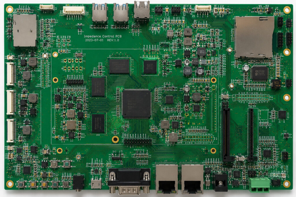
When many people design a PCB, they first focus on trace width, trace spacing, hole size, board layers, and component placement. They may think that as long as the DRC passes, the board should be fine.
However, if the board involves USB, Ethernet, DDR, LVDS, HDMI, RF signals, or high-speed communication interfaces, impedance can no longer be treated as a small detail.
The main purpose of impedance control is to ensure stable signal transmission on PCB traces. High-speed signals do not simply “travel from point A to point B.” They propagate along transmission lines. If the impedance is discontinuous, signal reflection, overshoot, ringing, packet loss, bit errors, and other problems may occur.
For example, the design may require a 90-ohm differential impedance or a 50-ohm single-ended impedance. But if the actual manufactured board has a large deviation, the board may still power on at first, yet become unstable when running high-speed data. In mild cases, communication may fail occasionally. In serious cases, the device may not be recognized, data may be lost, or the system may crash.
Many factors affect PCB impedance. It cannot be solved simply by changing one trace width. Common factors include trace width, trace spacing, copper thickness, dielectric thickness, dielectric constant, distance to the reference layer, stack-up structure, the layer where the impedance trace is routed, and the actual manufacturing capability of the PCB factory.
Therefore, high-speed PCB design cannot rely only on a value calculated by software. A reliable approach is to confirm the stack-up structure, material parameters, copper thickness, dielectric thickness, and impedance requirements with the PCB manufacturer before the design starts. After the design is completed, impedance coupons should also be made during production, and TDR testing should be used to confirm whether the actual impedance is within the allowed tolerance.
When some boards cannot be debugged successfully later, the issue may not always be the schematic or the software. Sometimes, the real problem is poor impedance control. Especially for high-speed communication boards, industrial control boards, medical equipment boards, server boards, and communication modules, if impedance is not controlled properly in the early stage, the cost of troubleshooting later can be very high.
So PCB design is not finished just because the traces are routed. For high-speed boards, impedance control should be involved before the design begins. One more confirmation in the early stage can save many rounds of rework later.