Not every PCB needs blind and buried vias, and using them does not automatically mean the design is better. A truly professional design is not about using the most complex process, but about using the right process only when it is needed.
Blind and buried vias mainly solve three problems: limited space, dense routing, and high signal requirements.
The first situation is when the BGA chip is too dense. Today, many main controllers, FPGAs, DSPs, CPUs, and communication chips are becoming smaller while having more pins. If the BGA pitch is relatively large, standard through-hole vias may still be enough for fanout. But for 0.5 mm, 0.4 mm, or even smaller-pitch BGAs, it becomes very difficult to route all signals using only through-hole vias. Via pads, trace width, and spacing all take up space, and the outer layers can quickly become blocked.
In this case, blind vias can route signals from the surface layer directly to the inner layers. This prevents the outer layers from becoming too crowded and allows the power, ground, and signal layers to be distributed more reasonably. For high-density BGA boards, blind vias are often not just an optional improvement, but a necessary design method.
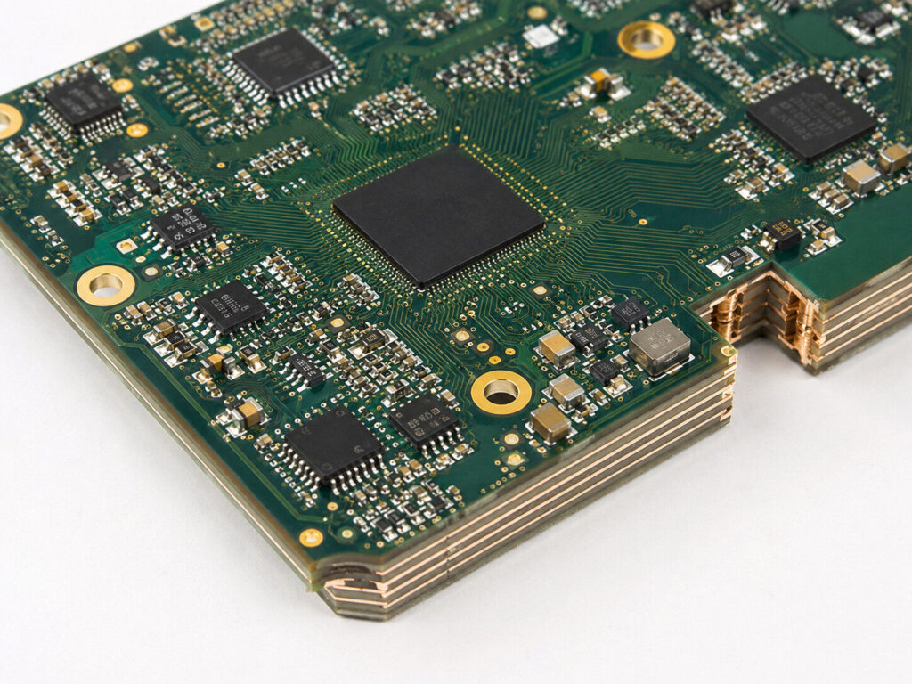
The second situation is when the PCB size is limited by the mechanical structure. Many customers already have a fixed product enclosure, so the PCB size cannot be changed, but they still want to add more functions. For example, they may need to add a communication module, sensor, power management circuit, or wireless function. As the number of components increases, the original routing space becomes insufficient. If standard through-hole vias are forced into the design, traces may become longer, more layers may be required, and signal quality may decrease. Blind and buried vias can reduce the space occupied by vias on unnecessary layers, allowing the limited PCB area to be used more efficiently.
The third situation is when there are many high-speed signals. In high-speed PCB design, a via is not just a simple hole used for connection. A via can introduce parasitic inductance and capacitance, and it may also cause impedance discontinuity. For high-speed differential signals, a long via stub can affect signal integrity. Since blind vias only connect the required layers, they can reduce unnecessary via structures and are more suitable for high-speed signals. In applications such as PCIe, DDR, high-speed Ethernet, and RF modules, blind and buried vias are often considered together with impedance control and stack-up design.
However, blind and buried vias also come with extra cost.
Their manufacturing process is more complex than standard PCBs and usually involves laser drilling, multiple lamination steps, and via filling or plating. The more complex the process, the higher the requirement for the PCB manufacturer, and the cost will also increase significantly. If the design is not planned properly in the early stage, such as unreasonable blind via layer structure, too small via diameter, unsuitable dielectric thickness, or unclear stack-up design, the project may face higher cost, longer lead time, or even manufacturing failure.
Therefore, whether a PCB needs blind and buried vias should not be decided simply because the customer wants an advanced process. It should be judged based on the real design requirements. Can the BGA be fanned out? Are the trace width and spacing enough? Is the layer count reasonable? Are there high-speed signals? Can the board thickness and stack-up support the design? Can the manufacturer meet the process requirements? These questions should be confirmed in advance.
For engineering projects, the biggest value of blind and buried vias is that they make designs possible when ordinary routing methods cannot meet the requirements. But they are not a universal solution, and more vias do not always mean a better design. A good PCB design must find the right balance between performance, cost, reliability, and manufacturing difficulty.
If your board is just a normal control board with low component density and low-speed signals, standard through-hole vias are usually enough. But if the project involves high-density BGA, high-speed signals, small mechanical size, or complex multilayer interconnections, then blind and buried vias are very likely a process that must be considered.