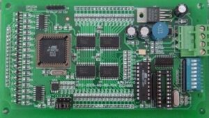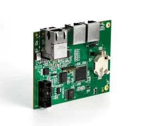

PIC microcontrollers power millions of industrial machines, medical devices, and automotive systems worldwide. When firmware is lost, locked, or needs recovery, this guide explains exactly what’s possible — and which recovery path applies to your chip family.
Key Takeaways
- PIC code protection (CP bit) prevents ICSP read access but can be bypassed via glitching (8-bit PICs: 20–50%), JTAG exploit (PIC32MX pre-2015: 70–90%), or chip-off (all families: 50–70%)
- Chip erase destroys firmware — it does NOT recover code; it enables reprogramming by resetting CP=0
- PIC32MX pre-2015 silicon has a known JTAG vulnerability; post-2015 silicon and PIC32MZ/MK are patched
- CP vs WRT: Code Protection blocks reading (recovery barrier); Write Protection blocks writing (NOT a recovery barrier)
- Family-specific difficulty: Easiest = PIC32MX pre-2015 (JTAG); Medium = 8-bit PIC16F/18F (glitching); Hardest = PIC32MZ/MK (<5% glitching)
Introduction: PIC Microcontrollers and the Firmware Recovery Challenge
PIC (Peripheral Interface Controller) microcontrollers, manufactured by Microchip Technology, are one of the world’s most widely deployed MCU families. First introduced in the 1970s, PIC chips now power everything from simple LED controllers to complex automotive ECUs, medical pumps, and industrial PLCs. With over 30 years of market presence, millions of PIC-based devices are still in active use — and when firmware is lost due to chip failure, obsolescence, or lack of source files, recovery becomes critical.
Unlike modern ARM-based microcontrollers (like STM32), which have standardized debug protocols, PIC microcontrollers use Microchip’s proprietary ICSP (In-Circuit Serial Programming) protocol. Each PIC family — 8-bit (PIC10/12/16/18), 16-bit (PIC24/dsPIC30/33), and 32-bit (PIC32) — implements code protection differently, with varying levels of security and recovery difficulty.
This article provides a comprehensive guide to PIC firmware recovery. We cover all major families, explain how the CP (Code Protection) bit works, detail extraction methods from direct ICSP read to voltage glitching to chip-off, and clarify common misconceptions (especially the chip erase myth). For broader MCU recovery context, see our MCU firmware recovery service hub article. For comparison with ARM-based MCUs, see our STM32 firmware recovery guide.
Understanding PIC Code Protection (CP Bit)
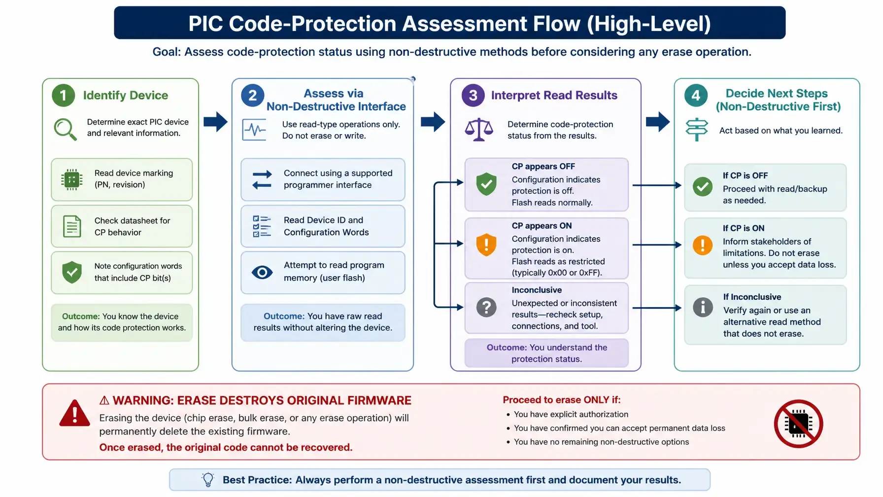
The primary protection mechanism on PIC microcontrollers is the CP (Code Protection) bit, stored in the device’s configuration word. When CP is enabled (CP=1), the PIC’s internal protection logic blocks read access to program memory via ICSP.
How the CP Bit Works
When CP = 0 (disabled, factory default):
- ICSP read commands work normally
- Programmers (PICkit, ICD) can read program memory, data EEPROM, and configuration bytes
- Full debugging and in-circuit emulation available
- This is the normal development configuration
When CP = 1 (enabled):
- ICSP read commands are blocked
- 8-bit PIC (PIC16F/18F): Read commands return 0x3FFF or 0xFF (unprogrammed flash value) instead of actual code
- 16-bit PIC (PIC24/dsPIC): Read commands return 0xFFFFFF
- 32-bit PIC32: JTAG/EJTAG access is disabled entirely
- The firmware is still present in flash memory, but internal protection circuitry intercepts and blocks read operations
- ICSP write and erase commands may still work (see “Chip Erase” section below)
CP vs WRT: Critical Distinction
PIC microcontrollers have two separate protection mechanisms that are often confused:
| Protection | Purpose | Effect on Recovery |
|---|---|---|
| CP (Code Protection) | Prevents reading program memory | This IS a recovery barrier — special techniques required |
| WRT (Write Protection) | Prevents writing to specific flash regions | This is NOT a recovery barrier — read operations still work |
Key point: If your PIC has WRT=1 but CP=0, the firmware can still be read normally via ICSP. WRT is commonly used to protect bootloader regions from accidental overwrite during field updates. It is not a security feature for firmware protection.
The Chip Erase Misconception
This is the most common misunderstanding about PIC firmware recovery.
When CP=1 is set, the PIC’s ICSP protocol still allows a chip erase (bulk erase) command. Executing this command:
- Erases the entire program memory (flash)
- Erases data EEPROM
- Resets the CP bit to 0 (disabled)
- Your original firmware is permanently destroyed
Chip erase does NOT recover firmware — it destroys it. This operation is designed for locked-out developers who need to reprogram the chip, not for someone trying to extract existing code. If you have a CP=1 protected PIC and need to recover the firmware (not destroy it), voltage glitching, JTAG exploit (PIC32MX), or chip-off is required.
PIC Family Overview and Recovery Difficulty
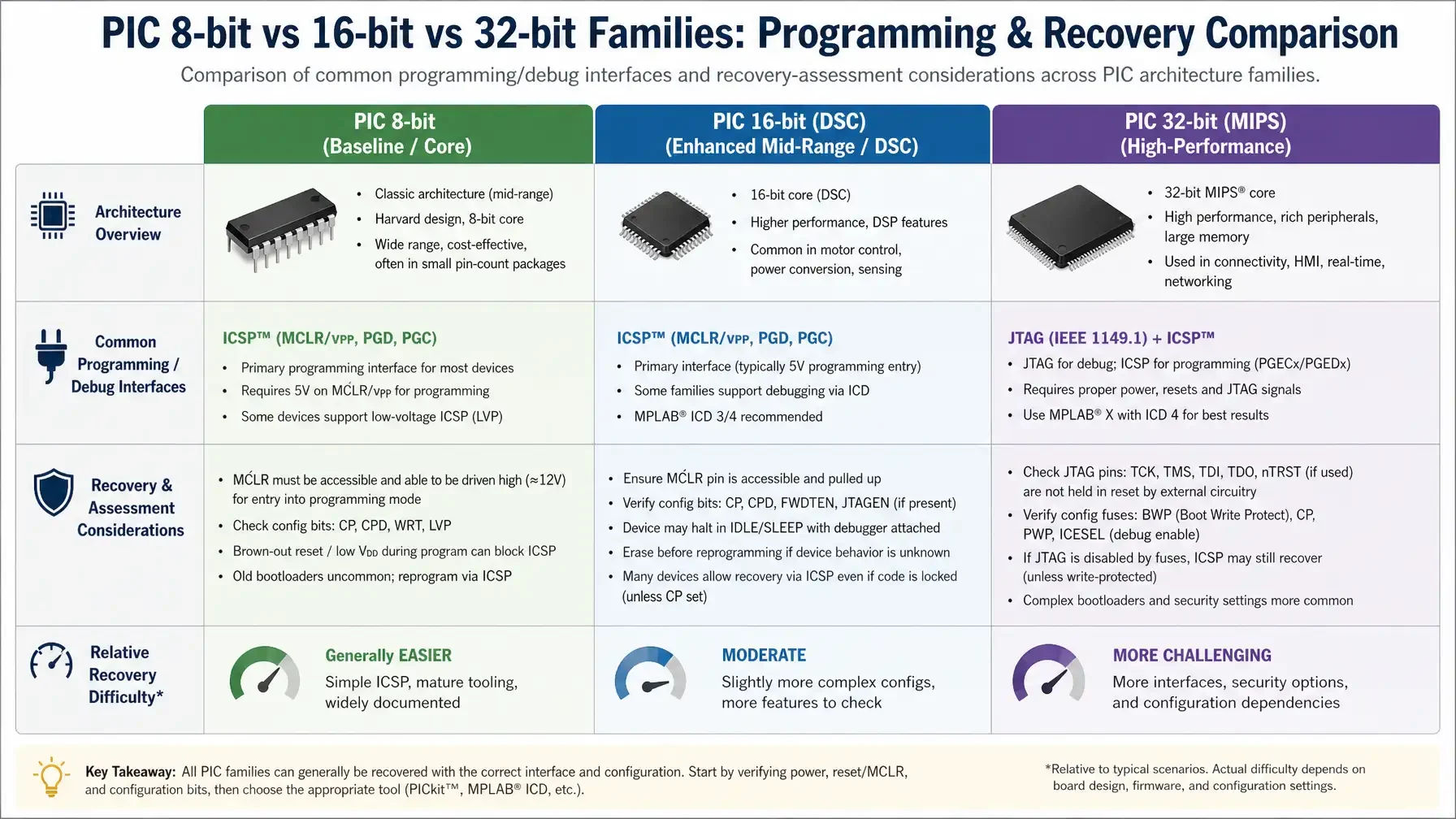
PIC microcontrollers span three major architecture families, each with different code protection implementations and recovery difficulty.
8-bit PIC (PIC10/12/16/18)
| Family | Flash Size | ICSP Protocol | Protection | Recovery Difficulty |
|---|---|---|---|---|
| PIC10F | 384 B – 1.5 KB | 2-wire ICSP | CP bit | Medium (small die, difficult chip-off) |
| PIC12F | 512 B – 8 KB | 2-wire ICSP | CP bit | Easy-Medium (glitching 30–50%) |
| PIC16F | 512 B – 64 KB | 2-wire ICSP | CP bit | Easy-Medium (varies by series) |
| PIC18F | 4 KB – 128 KB | 2-wire ICSP | CP bit | Medium (newer K-series more hardened) |
Most common recovery requests: PIC16F877A, PIC16F88, PIC18F4550, PIC18F452
Glitching success rate:
- PIC16F87x/88x (older dies, pre-2010): 40–60%
- PIC16F1xxx (enhanced midrange, post-2010): 10–20%
- PIC18F2xx/4xx (pre-2010): 30–50%
- PIC18FxxK series (post-2010): 10–20%
The newer enhanced midrange (PIC16F1xxx) and K-series (PIC18FxxK) have more robust CP checking logic, making them less vulnerable to timing-based attacks.
16-bit PIC (PIC24/dsPIC30/dsPIC33)
| Family | Flash Size | ICSP Protocol | Protection | Recovery Difficulty |
|---|---|---|---|---|
| PIC24F | 4 KB – 512 KB | 4-wire ICSP | GCP (General Segment) | Hard (5–15% glitching) |
| dsPIC30F | 12 KB – 256 KB | 4-wire ICSP | GCP | Hard (5–15% glitching) |
| dsPIC33F | 16 KB – 1 MB | 4-wire ICSP | GCP | Hard (5–15% glitching) |
Protection mechanism: Instead of a single CP bit, 16-bit PICs use General Segment Code Protection (GCP). This operates similarly but is implemented in hardware with more robust timing checks.
Key difference: 16-bit PICs use a 4-wire ICSP protocol (PGC/PGD + two additional control lines) instead of the 8-bit family’s 2-wire protocol. The enhanced ICSP implementation makes timing-based glitching attacks more difficult.
Glitching success rate: 5–15% (significantly lower than 8-bit PICs)
Recommended recovery path: Chip-off / IC decapsulation (50–70% success rate) is more reliable than glitching for 16-bit families.
32-bit PIC (PIC32MX/MZ/MK/MM)
| Family | Flash Size | Debug Interface | Protection | Recovery Difficulty |
|---|---|---|---|---|
| PIC32MX | 16 KB – 512 KB | ICSP + JTAG | CP bit + BWP | Pre-2015: Easy (JTAG exploit 70–90%) Post-2015: Hard (glitching 5–10%) |
| PIC32MZ | 128 KB – 2 MB | ICSP + JTAG | CP + Secure Boot | Very Hard (<5% glitching) |
| PIC32MK | 256 KB – 1 MB | ICSP + JTAG | CP + Enhanced | Very Hard (<5% glitching) |
Critical vulnerability: PIC32MX families manufactured before 2015 have a well-documented JTAG exploit (see dedicated section below). Post-2015 silicon has this patched.
Firmware Extraction Methods for PIC
Method 1: Direct ICSP Read (CP=0 Only)
When applicable: CP bit = 0 (disabled, factory default)
Process:
- Connect ICSP programmer (PICkit 4, ICD 4, or compatible) to target PIC
- Connect ICSP pins: PGC (clock), PGD (data), MCLR (reset), VDD, GND
- Use MPLAB X IPE or command-line tool (pk2cmd) to read program memory
- Export to Intel HEX or binary format
Success rate: 100% if no code protection is enabled.
Non-destructive: Yes. The PIC can continue operating normally after read.
Turnaround: 1–2 days
Cost range: $200–$400
Method 2: Chip Erase (NOT Recovery — Clarification)
This is NOT a firmware recovery method. We include it here to clarify the common misconception.
When CP=1 is set, executing a chip erase command via ICSP:
- Erases all program memory and data EEPROM
- Resets CP bit to 0
- Original firmware is GONE FOREVER
- Chip can now be reprogrammed with new firmware
Use case: You are a developer who has lost the source code and wants to reprogram the chip for a different application. This is device reprogramming, not firmware extraction.
If you need to recover existing firmware: Do NOT use chip erase. Use glitching, JTAG exploit, or chip-off instead.
Method 3: Voltage Glitching (CP=1, 8-bit PICs)
Purpose: Induce a timing fault during the CP check to momentarily bypass protection.
Principle: When a PIC boots or enters ICSP mode, it reads the configuration word (including the CP bit) from flash memory. This read operation takes approximately 50–200 nanoseconds. By introducing a precise voltage glitch (drop VDD from 5V to ~2V for 10–50 ns) during this window, we can cause a bit flip: CP=1 → CP=0 momentarily. If the glitch succeeds, the PIC’s protection check fails, and one ICSP read cycle completes before protection re-engages.
Target families: 8-bit PIC16F and PIC18F (pre-2010 dies most vulnerable)
Success rate:
- PIC16F87x/88x: 40–60%
- PIC18F2xx/4xx (pre-2010): 30–50%
- PIC16F1xxx / PIC18FxxK (post-2010): 10–20%
Factors affecting success:
- Die revision: Later revisions have more robust CP checking
- Temperature: Running the PIC at lower temperatures (0–10°C) can increase vulnerability
- Glitching equipment: Professional setups (ChipWhisperer Pro) outperform DIY approaches
- Randomness: Even with ideal conditions, multiple attempts are often needed
Tools: ChipWhisperer Lite/Pro, custom ICSP glitching hardware, oscilloscope with trigger control
Turnaround: 3–5 days (multiple attempts usually required)
Cost range: $800–$1,500
Limitations:
- Does NOT work reliably on 16-bit PIC (PIC24/dsPIC) — different timing, more robust protection
- Does NOT work on 32-bit PIC32 (different architecture)
Method 4: PIC32MX JTAG Exploit (Pre-2015 Silicon Only)
Applies to: PIC32MX1xx/2xx/3xx/4xx/5xx/6xx/7xx families manufactured before 2015.
Vulnerability: The JTAG TAP (Test Access Port) controller on early PIC32MX silicon has a boundary-scan vulnerability. By entering a specific JTAG instruction sequence via the TAP controller, the CP check can be bypassed, allowing EJTAG (MIPS debug interface) memory read commands to access program flash.
How it works:
- Connect JTAG interface (TCK/TDI/TDO/TMS) to PIC32MX
- Use OpenOCD with custom PIC32 EJTAG scripts
- Enter JTAG bypass mode via specific TAP instruction sequence
- Send EJTAG
PRACC(Processor Access) commands to read memory directly - Dump flash contents to file
Success rate: 70–90% on vulnerable silicon (pre-2015 PIC32MX)
Silicon revision identification:
- Check the manufacture date code on the chip marking (format: YYWW = year + week)
- If manufacture date is before 2015 (date code <1501), likely vulnerable
- If unsure, send us a photo of the chip marking for assessment
Patched families:
- PIC32MX post-2015 (date code ≥1501): Patched
- PIC32MZ (all revisions): Never vulnerable
- PIC32MK (all revisions): Never vulnerable
- PIC32MM (all revisions): Never vulnerable
Tools: OpenOCD, custom JTAG adapter, EJTAG scripts
Turnaround: 2–3 days
Cost range: $600–$1,200
Important: This is a well-documented vulnerability that Microchip has acknowledged and patched. Using this method on pre-2015 silicon for authorized firmware recovery is legal under DMCA Section 1201(f) (reverse engineering exception). See our PCB reverse engineering authorization article for legal context.
Method 5: Chip-Off / IC Decapsulation (All Families, All Protection Levels)
When required: Code protection enabled AND glitching/exploits fail or are not applicable.
Process:
- Chip removal: Use hot-plate rework station or IR reflow to remove PIC from PCB
- Decapsulation: Chemical decapsulation (fuming nitric acid for plastic packages) or plasma etching (for QFN with exposed die pad) to expose the die
- Die imaging: Photograph die under microscope to locate flash memory array
- Microprobing: Use microprobe station with nanometer positioning to contact flash memory cells directly
- Bit-level read: Read flash array cell-by-cell, reconstruct program memory
Success rate: 50–80% (depends on die size, package type, decapsulation quality)
Challenges by package type:
- SOIC-8/14/18/28 (8-bit PIC): Easy rework, easy decapsulation, high success
- TQFP-44/64/100 (PIC18F/PIC24F/PIC32): Medium rework, medium decapsulation
- QFN-28/44/64: Hard rework (no leads), exposed die pad helps
- SOT-23-6 (PIC10F): Very small die, difficult to probe
- BGA (PIC32MZ): Very hard rework, multi-layer die structure
Turnaround: 7–14 days (labor-intensive process)
Cost range: $2,000–$5,000
Note: This method is destructive to the chip (package destroyed, die exposed). The PCB itself is not damaged and can be fitted with a new programmed PIC if needed.
PIC32MX JTAG Exploit Deep-Dive
Because the PIC32MX JTAG vulnerability is so effective (70–90% success rate) and frequently misunderstood, we provide additional detail here.
What Is the JTAG TAP Controller?
JTAG (Joint Test Action Group, IEEE 1149.1) is a standard debug interface used in many 32-bit microcontrollers. It provides boundary-scan testing and in-circuit debugging via a Test Access Port (TAP) controller. The TAP controller is a state machine that responds to specific instruction sequences sent via the JTAG pins (TCK/TDI/TDO/TMS).
The Vulnerability
On PIC32MX families manufactured before 2015, the TAP controller’s EJTAG (MIPS-specific JTAG extension) implementation has a flaw: the CP bit check occurs after EJTAG memory access commands are processed. By entering a specific TAP state (EJTAG debug mode) before the CP check completes, we can read memory directly.
Why Only Pre-2015 Silicon?
Microchip became aware of this vulnerability in 2014 and released new silicon revisions in 2015 with the TAP controller redesigned. The CP check now occurs before EJTAG commands are processed. Post-2015 PIC32MX silicon, as well as all PIC32MZ/MK/MM families, implement CP at the hardware level earlier in the boot sequence.
How to Determine If Your PIC32MX Is Vulnerable
Check the chip marking for the manufacture date code:
PIC32MX795F512L-80I/PT
         ↓
  [Silicon revision letter + date code YYWW]

Example: "1435" = 2014, Week 35 → Vulnerable
Example: "1612" = 2016, Week 12 → Patched
If you’re unsure, send us a clear photo of the chip marking. We can identify the manufacture date and assess vulnerability.
Is This Legal?
Yes, for authorized firmware recovery. DMCA Section 1201(f) provides an exception for reverse engineering for interoperability purposes, which includes firmware extraction from devices you own or have authorization to service. See our PCB reverse engineering authorization guide for documentation requirements.
How to Identify Your PIC
Look at the top marking on the IC package. PIC part numbers follow this format:
PIC [Family] [Series] [Pin Count] [Package] [Temp] [Speed]
Examples
PIC16F877A-I/P:
PIC16F= PIC16F family (8-bit enhanced midrange)877= Series 877A= Revision AI= Industrial temperature range (-40 to +85°C)P= PDIP (Plastic Dual In-line Package), 40-pin
PIC18F4550-I/PT:
PIC18F= PIC18F family (8-bit high-end)4550= Series 4550I= Industrial temperaturePT= TQFP (Thin Quad Flat Pack), 44-pin
PIC24FJ128GA010-I/PT:
PIC24F= PIC24F family (16-bit general-purpose)J= Sub-family J128= 128 KB flashGA010= Series identifierI/PT= Industrial temp, TQFP-100
PIC32MX795F512L-80I/PT:
PIC32MX= PIC32MX family (32-bit MIPS)795= Series 795F512= 512 KB flashL= Low pin count variant80= 80 MHz max frequencyI/PT= Industrial temp, TQFP-100
Quick Family Identification
| Prefix | Architecture | Example |
|---|---|---|
| PIC10F | 8-bit baseline | PIC10F200 |
| PIC12F | 8-bit midrange | PIC12F675 |
| PIC16F | 8-bit midrange/enhanced | PIC16F877A |
| PIC18F | 8-bit high-end | PIC18F4550 |
| PIC24 | 16-bit | PIC24FJ128GA010 |
| dsPIC30 | 16-bit DSP | dsPIC30F4011 |
| dsPIC33 | 16-bit DSP | dsPIC33FJ128GP802 |
| PIC32MX | 32-bit MIPS | PIC32MX795F512L |
| PIC32MZ | 32-bit MIPS | PIC32MZ2048EFH144 |
If you’re unsure, take a clear photo of the chip marking and send it to us. We’ll identify the family, assess code protection likelihood, and provide a recovery assessment.
Frequently Asked Questions
1. Can I recover code from a code-protected PIC microcontroller?
It depends on the PIC family and code protection configuration:
- CP=0 (disabled): Yes, 100% success via direct ICSP read.
- CP=1, 8-bit PIC16F/18F: Yes, 20–50% via voltage glitching (varies by family and die revision), or 50–70% via chip-off/decapsulation.
- CP=1, 16-bit PIC24/dsPIC: Yes, but more difficult. Glitching success rate 5–15%. Chip-off recommended (50–70%).
- CP=1, PIC32MX pre-2015: Yes, 70–90% via JTAG exploit.
- CP=1, PIC32MX post-2015: Yes, but difficult. Glitching 5–10% or chip-off required.
- CP=1, PIC32MZ/MK: Yes, but very difficult. Glitching <5%. Chip-off recommended (50–70%).
Contact us with your PIC part number for a specific assessment.
2. What is PIC code protection (CP bit) and how does it work?
The CP (Code Protection) bit is a configuration setting in PIC microcontrollers that prevents unauthorized reading of program memory via ICSP.
When CP=0 (disabled): ICSP read commands work normally, providing full access to program memory, data EEPROM, and configuration.
When CP=1 (enabled): ICSP read commands are blocked. 8-bit PICs return 0x3FFF or 0xFF instead of actual code. 16-bit PICs return 0xFFFFFF. 32-bit PIC32 disables JTAG/EJTAG access entirely. The firmware is still in flash, but internal protection logic intercepts and blocks read operations.
CP can only be removed by chip erase, which destroys the existing firmware.
3. Does chip erase recover my PIC firmware?
No. Chip erase DESTROYS your firmware, not recovers it.
When you send a chip erase command to a CP=1 protected PIC:
- The chip erases all program memory and data EEPROM
- The CP bit resets to 0 (disabled)
- Your original firmware is permanently gone
- You can now program new firmware to the chip
This is a recovery pathway for locked-out developers who want to reprogram the chip — not for someone who needs to extract existing firmware.
4. Which PIC families are easiest vs hardest to recover?
| Difficulty | Family | Reason |
|---|---|---|
| Easiest | PIC32MX (pre-2015) | Known JTAG exploit; 70–90% success rate |
| Easy | PIC16F87x/88x (older) | More vulnerable to glitching; 40–60% success |
| Medium | PIC18F2xx/4xx (pre-2010) | Moderate glitching success; 30–50% |
| Medium | PIC16F1xxx / PIC18FxxK | Newer silicon, more hardened; 10–20% glitching |
| Hard | PIC24F / dsPIC30/33 | Different ICSP protocol, better protection; 5–15% glitching |
| Hard | PIC32MX (post-2015) | Patched JTAG exploit; 5–10% glitching |
| Hardest | PIC32MZ / MK | Secure Boot, strong protection; <5% glitching |
For all families, chip-off/IC decapsulation remains an option with 50–70% success rate.
5. Can PIC32 firmware be recovered with code protection enabled?
It depends on the specific PIC32 family and manufacture date:
PIC32MX (pre-2015 silicon):
- Yes, with high success rate (70–90%) via JTAG exploit
- The JTAG TAP controller has a boundary-scan vulnerability that allows EJTAG memory read
- This exploit is well-documented and reliable on vulnerable silicon
PIC32MX (post-2015 silicon):
- JTAG exploit has been patched
- Voltage glitching success rate is 5–10%
- Chip-off/IC decapsulation is the more reliable option (50–70%)
PIC32MZ/MK (all revisions):
- JTAG exploit never existed on these families
- Additional security features (Secure Boot, enhanced protection)
- Glitching success rate <5%
- Chip-off is the primary recovery path (50–70%)
6. What is the difference between CP and WRT on PIC?
These are two different protection mechanisms:
CP (Code Protection):
- Purpose: Prevents reading program memory
- When enabled: ICSP read commands are blocked
- Effect on recovery: This IS a recovery barrier; special techniques required
WRT (Write Protection):
- Purpose: Prevents writing to specific program memory regions
- When enabled: ICSP write commands to protected regions are blocked
- Effect on recovery: This is NOT a recovery barrier; read operations still work
Key distinction: WRT only protects against modification, not reading. If your PIC has WRT=1 but CP=0, the firmware can still be read normally via ICSP.
7. How do I identify which PIC family I have?
Look at the top marking on the IC package. The part number format is:
PIC [Family] [Series] [Pin] [Package] [Temp] [Speed]
Examples:
- PIC16F877A-I/P: PIC16F family (8-bit), 877 series, 40-pin PDIP
- PIC18F4550-I/PT: PIC18F family (8-bit), 4550 series, 44-pin TQFP
- PIC24FJ128GA010-I/PT: PIC24F family (16-bit), 128KB flash, 100-pin TQFP
- PIC32MX795F512L-80I/PT: PIC32MX family (32-bit), 512KB flash, 100-pin TQFP
If you’re unsure, take a clear photo of the chip marking and send it to us for identification.
8. Can PIC16F and PIC18F be glitched to bypass CP?
Yes, but with varying success rates depending on the specific series and die revision.
PIC16F families:
- PIC16F87x/88x (older dies, pre-2010): 40–60% success rate
- PIC16F1xxx (newer enhanced midrange): 10–20% success rate
PIC18F families:
- PIC18F2xx/4xx (pre-2010): 30–50% success rate
- PIC18FxxK series (post-2010): 10–20% success rate
If glitching fails, chip-off/IC decapsulation is the next option (50–70% success rate).
9. What tools do you use for PIC firmware extraction?
We use a combination of professional-grade tools:
ICSP programmers: PICkit 4, ICD 4, custom ICSP adapters with enhanced timing control
Software: MPLAB X IPE, pk2cmd, OpenOCD (for PIC32 JTAG), custom ICSP protocol implementations
Glitching equipment: ChipWhisperer Lite/Pro, custom voltage/clock glitching setups, oscilloscope with trigger control
Chip-off equipment: Hot-plate rework station, IR reflow, precision tools
Decapsulation lab: Chemical decapsulation (fuming nitric acid), plasma etching, microprobe station with nanometer positioning
10. Is PIC easier or harder to recover than STM32?
It varies by family and protection scenario:
| Aspect | PIC | STM32 |
|---|---|---|
| Protection mechanism | CP bit in config word | RDP levels 0/1/2 |
| Glitching (8-bit) | 20–50% (PIC16F/18F) | N/A (STM32 is 32-bit only) |
| Glitching (32-bit) | 5–10% (PIC32MX post-2015) | 20–40% (STM32F1/F4) |
| Known exploits | PIC32MX JTAG (pre-2015 only) | STM32F1 bootloader (pre-rev3) |
| Decap difficulty | Easy (8-bit), Medium (32-bit) | Medium (F1/F4), Hard (H7) |
Summary: Old PIC32MX (pre-2015) is easier than STM32 (JTAG exploit 70–90%). 8-bit PIC is moderate difficulty. Modern PIC32MZ is similar to STM32H7 (both difficult). STM32F4 generally easier than modern PIC32.
Get a Free PIC Code Recovery Assessment
Send us your PIC part number and a photo of the chip marking. We’ll identify the family, assess code protection likelihood, estimate recovery difficulty, and provide a fixed-price quote.
What we need:
- PIC part number (from chip marking)
- Photo of chip top marking (for manufacture date and silicon revision)
- Brief description of the device (industrial controller, medical device, automotive module, etc.)
- Authorization documentation (proof of ownership or authorization to service)
What you’ll receive:
- Family identification and technical specifications
- Recovery method recommendation (ICSP / glitching / JTAG exploit / chip-off)
- Success rate estimate
- Turnaround time estimate
- Fixed-price quote (no hidden fees)
For broader MCU recovery context, see our MCU firmware recovery service hub. For comparison with ARM-based MCUs, see our STM32 firmware recovery and AVR firmware recovery guides. If chip-off is required, see our IC decapsulation service for details on the physical extraction process.
All firmware recovery work requires authorization documentation. See our PCB reverse engineering authorization guide for legal requirements and documentation templates.